Distance measurement with ultrasonic sensor HC-SR04 using the Arduino with a serial connection (Python)
This tutorial guides you through wiring a HC-SR04 ultrasonic sensor to an Arduino Nano and connect this via a serial connection to a Raspberry Pi. A distance to an object can then be measured by a run-time measurement.
Before starting you should read What is a ROS Wrapper?, Write a ROS Wrapper (Python) and Package and Test Your Driver.
In this project, an ultrasonic sensor module (HC-SR04) is put into operation. The working principle of an HC-SR04 is explained. It is also described how a measurement with ultrasound works and on which essential factors it depends. For the commissioning of the sensor, we take an serial connected Arduino to a Raspberry Pi as an example.
What is ultrasonic?
Ultrasound is a high-pitched sound wave whose frequency exceeds the audible range of human hearing.

Humans can hear sound waves that vibrate in the range of about 20 times a second (a deep rumbling noise) to 20,000 times a second (a high-pitched whistle). However, ultrasound has a frequency of more than 20,000 Hz and is therefore inaudible to humans.
What is an ultrasonic sensor?
An ultrasonic sensor is generally a sensor that determines the distance to an object via a run-time measurement. It cannot classify which object is located at this distance. As shown in the following figure, the ultrasonic sensor emits ultrasonic waves. This is where it gets its name. At an object, these ultrasonic waves are reflected and reflected back. A membrane on the sensor receives these ultrasonic waves. Since it is known how fast the carrier medium is, a distance to the object is determined based on the time interval between sending and receiving the ultrasonic waves. We will take a closer look at what this means in concrete terms below.
The HC-SR04 sensor
An HC-SR04 ultrasonic distance sensor actually consists of two ultrasonic transducers. Ultrasonic transducers and ultrasonic sensors are devices that generate or sense ultrasound energy. They can be divided into three broad categories: transmitters, receivers and transceivers. Transmitters convert electrical signals into ultrasound, receivers convert ultrasound into electrical signals, and transceivers can both transmit and receive ultrasound.
The HC-SR04 sensor looks like this:
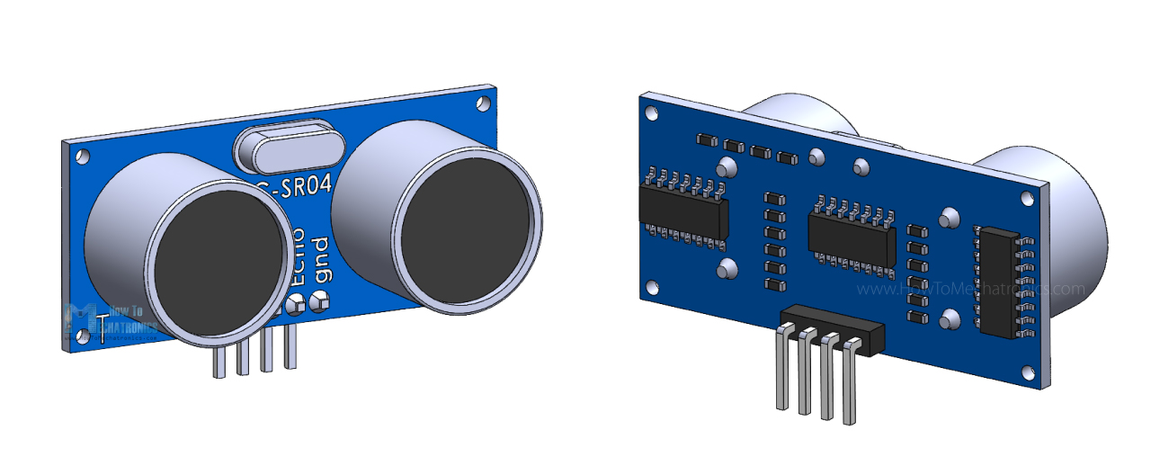
One acts as a transmitter that converts the electrical signal into 40 KHz ultrasonic sound pulses. The other acts as a receiver and listens for the transmitted pulses.
When the receiver receives these pulses, it produces an output pulse whose width is proportional to the distance of the object in front.
This sensor provides excellent non-contact range detection between 2 cm to 400 cm (~13 feet) with an accuracy of 3 mm.
Since it operates on 5 volts, it can be connected directly to a Raspberry Pi or any other 5V logic microcontroller.
Technical Specifications
Operating Voltage |
DC 5V |
Operating Current |
15mA |
Operating Frequency |
40KHz |
Max Range |
4m |
Min Range |
2cm |
Ranging Accuracy |
3mm |
Measuring Angle |
15 degree |
Trigger Input Signal |
10µS TTL pulse |
Dimension |
45 x 20 x 15mm |
Pinout
Let’s take a look at its pinout.
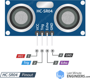
VCC supplies power to the HC-SR04 ultrasonic sensor. You can connect it to one of the 5V outputs from your Raspberry Pi.
Trig (Trigger) pin is used to trigger ultrasonic sound pulses. By setting this pin to HIGH for 10µs, the sensor initiates an ultrasonic burst.
Echo pin goes high when the ultrasonic burst is transmitted and remains high until the sensor receives an echo, after which it goes low. By measuring the time the Echo pin stays high, the distance can be calculated.
GND is the ground pin. Connect it to the ground of your Raspberry Pi.
Operating principle
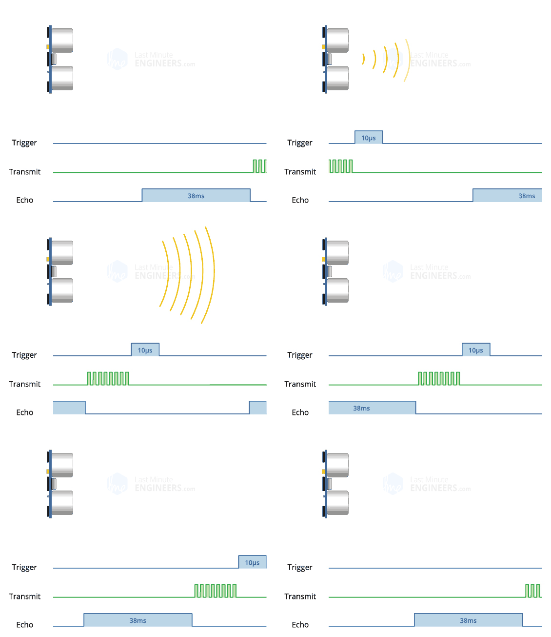
It all starts when the trigger pin is set HIGH for 10µs. In response, the sensor transmits an ultrasonic burst of eight pulses at 40 kHz. This 8-pulse pattern is specially designed so that the receiver can distinguish the transmitted pulses from ambient ultrasonic noise.
These eight ultrasonic pulses travel through the air away from the transmitter. Meanwhile the echo pin goes HIGH to initiate the echo-back signal.
If those pulses are not reflected back, the echo signal times out and goes low after 38ms (38 milliseconds). Thus a pulse of 38ms indicates no obstruction within the range of the sensor.
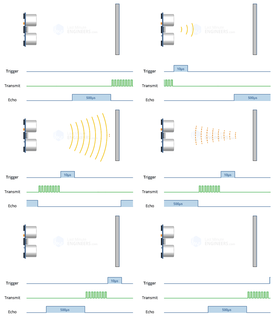
If those pulses are reflected back, the echo pin goes low as soon as the signal is received. This generates a pulse on the echo pin whose width varies from 150 µs to 25 ms depending on the time taken to receive the signal.
Calculating the distance
The width of the received pulse is used to calculate the distance from the reflected object. This can be worked out using the simple distance-speed-time equation we learned in high school. An easy way to remember the equation is to put the letters in a triangle.
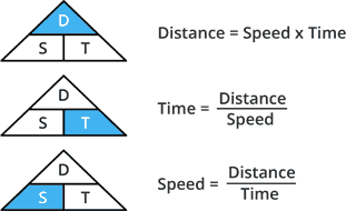
Let us take an example to make it more clear. Suppose we have an object in front of the sensor at an unknown distance and we receive a pulse of 500µs width on the echo pin. Now let’s calculate how far the object is from the sensor. For this we will use the below equation.
Distance = Speed x Time
Here we have the value of time i.e. 500 µs and we know the speed. Of course it’s the speed of sound! It is 340 m/s. To calculate the distance we need to convert the speed of sound into cm/µs. It is 0.034 cm/μs. With that information we can now calculate the distance!
Distance = 0.034 cm/µs x 500 µs
But we’re not done yet! Remember that the echo pulse indicates the time it takes for the signal to be sent and reflected back. So to get the distance, you have to divide your result by two.
Distance = (0.034 cm/µs x 500 µs) / 2
Distance = 8.5 cm
Now we know that the object is 8.5 cm away from the sensor.
How to wire the HC-SR04 and the Arduino to the Raspberry Pi?
Please have a look at the following diagram:
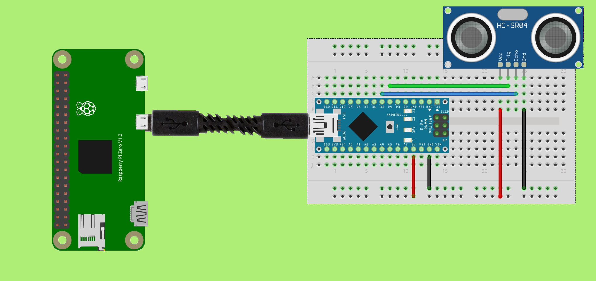
Admittedly, in the illustration we see a Raspberry Pi Zero and an Arduino NANO, but both the different Raspberry Pis and the different Arduinos are identical in construction. So we could wire up a Raspberry Pi 3 Model B+ and an Arduino UNO in the same way.
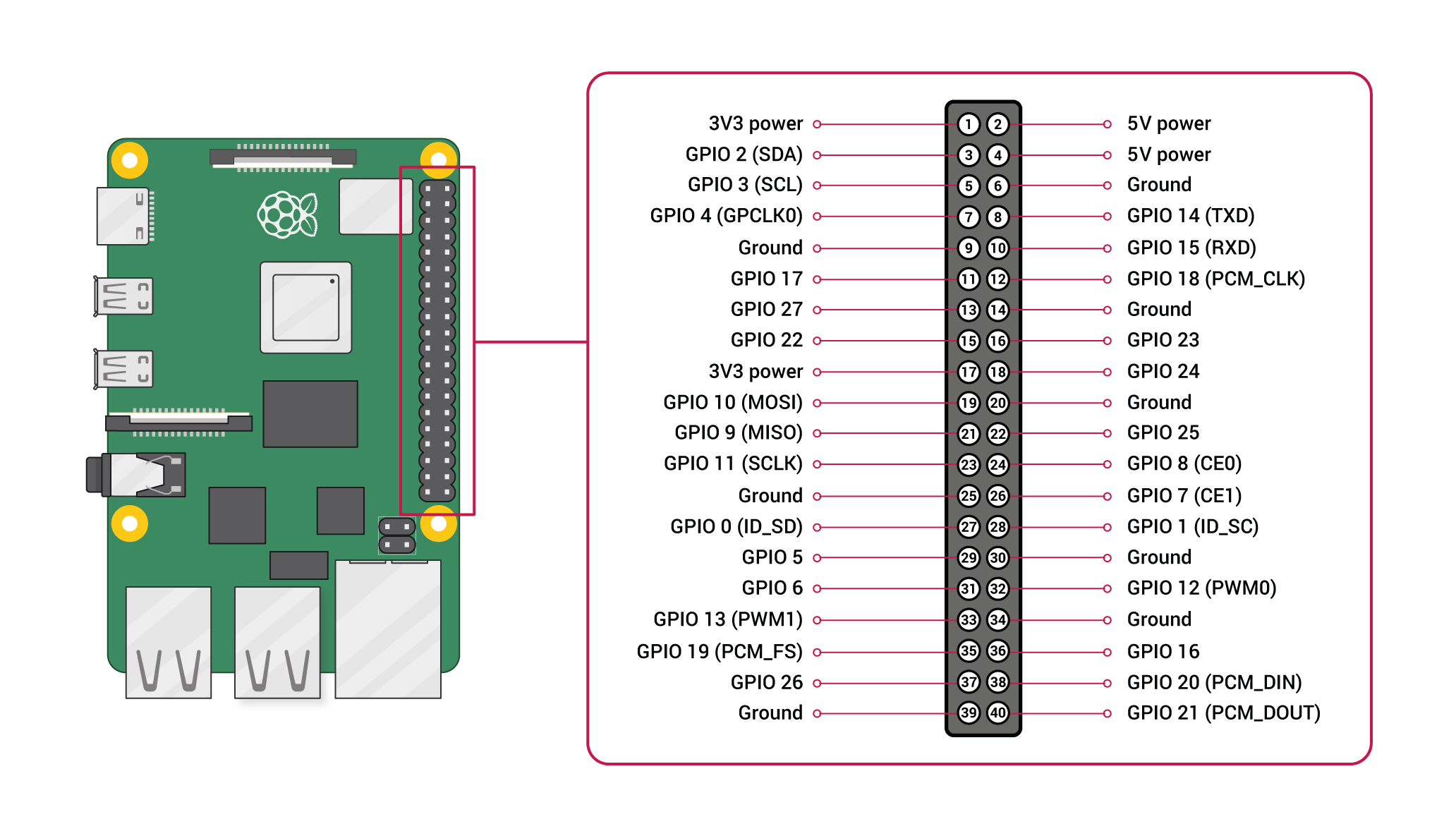
This is how the pinout of the Raspberry Pi looks like:
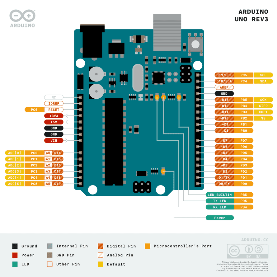
And this is how the pinout of the Arduino looks like:
The structure is such that the Arduino serves as a driver board for the sensor and serially forwards the data to the Raspberry Pi, since it runs ROS. With this example it will be explained how driver boards are used to connect hardware components. In robotics there are often boards for motors or servo motors.
At first you have to connect the Raspberry Pi with your Arduino. If you use a Raspberry Pi Zero there you need micro USB at this side and if you use a Raspberry Pi then you need USB-A. If you use an Arduino NANO you need mini USB and if you use Arduino UNO you need USB B. This of course means that you need different cables depending on the Arduino or Raspberry Pi model. In any case, use a suitable USB cable.
In our example we now connect the HC-SR04 to our Arduino. I have used the Arduino NANO for this:
Sensor pin |
Arduino pin |
VCC |
5V |
GND |
GND |
TRIG |
D4 |
ECHO |
D5 |
Unlike the Raspberry Pi, we now no longer need to use a voltage divider. This is because the Arduino works with 5V instead of 3.3V on its digital pins.
Preparations on the Raspberry Pi
We need to install pySerial. PySerial can be installed from PyPI:
python3 -m pip install pyserial
Programming the distance measurement
At this point we need to program two things: An Arduino Sketch that ultimately performs the measurement on the Arduino and writes the data serially, and a Python program on the Raspberry Pi that reads the serially written data.
The Arduino Sketch
For data transfer, we have several options at the end. Serial writing and reading always means that some time is lost due to the weak performance of a simple Arduino. This is our bottleneck. Therefore I show different variants how we can tackle this.
In the Arduino sketch I was using “Serial.Print“, although this is the simplest way of communicating data, it isn’t particularly efficient as it passes everything as an ASCII string. This clearly has some performance issues, the code must have to convert the data to a string and then passing it as ASCII could be inefficient e.g. 24.564 would be 5 bytes as a string plus a newline character but only 4 as a float. I ran a number of tests, I tried using a long instead of a float on the Arduino and passing it to Python which converts it to a float and also rounding the value to a whole number.
Float
const int trigger = 4;
const int echo = 5;

long timeElapsed = 0;
float distance = 0;

void setup() {
    pinMode(trigger, OUTPUT);
    pinMode(echo, INPUT);
    Serial.begin(115200);
}

void loop() {
    // Clear trigger
    digitalWrite(trigger,LOW);
    delayMicroseconds(2);

    // send 10 microseond trigger
    digitalWrite(trigger, HIGH);
    delayMicroseconds(10);
    digitalWrite(trigger, LOW);

    // time to get echo
    timeElapsed = pulseIn(echo, HIGH);

    // convert time to distance
    // Divide by 1000000 (convert microseconds to seconds)
    // Divide by 2 for distance there and back
    // Multiply by speed of sound 34300cm/s
    distance = (float)timeElapsed / 1000000 / 2 * 34300; // in cm

    Serial.print(distance);

    delay(500);
}
This code works basically the same as my Python code it initializes an input pin and an output pin, it then sends a 10 micro seconds pulse on the trigger and waits for the echo to signal the “echo” pin. Arduino has the function “pulseIn” function which returns the time in microseconds when a pin changes to a specified state (HIGH/LOW), instead of timing a loop in Python. The time elapsed is then converted to a distance and the result is written to the serial port. In this simple example the code outputs a human readable string.
Long
const int trigger = 4;
const int echo = 5;

long timeElapsed = 0;
float distance = 0;

void setup() {
    pinMode(trigger, OUTPUT);
    pinMode(echo, INPUT);
    Serial.begin(115200);
}

void loop() {
    // Clear trigger
    digitalWrite(trigger,LOW);
    delayMicroseconds(2);

    // send 10 microseond trigger
    digitalWrite(trigger, HIGH);
    delayMicroseconds(10);
    digitalWrite(trigger, LOW);

    // time to get echo
    timeElapsed = pulseIn(echo, HIGH);

    // convert time to distance
    // Divide by 1000000 (convert microseconds to seconds)
    // Divide by 2 for distance there and back
    // Multiply by speed of sound 34300cm/s
    unsigned long distance = timeElapsed / 2 * 343; // in cm

    Serial.print(distance);

    delay(500);
}
Long Whole Number
const int trigger = 4;
const int echo = 5;

long timeElapsed = 0;
float distance = 0;

void setup() {
    pinMode(trigger, OUTPUT);
    pinMode(echo, INPUT);
    Serial.begin(115200);
}

void loop() {
    // Clear trigger
    digitalWrite(trigger,LOW);
    delayMicroseconds(2);

    // send 10 microseond trigger
    digitalWrite(trigger, HIGH);
    delayMicroseconds(10);
    digitalWrite(trigger, LOW);

    // time to get echo
    timeElapsed = pulseIn(echo, HIGH);

    // convert time to distance
    // Divide by 1000000 (convert microseconds to seconds)
    // Divide by 2 for distance there and back
    // Multiply by speed of sound 34300cm/s
    unsigned long distance = timeElapsed / 2 * 343 / 10000; // in cm

    Serial.print(distance);

    delay(500);
}
Float Binary
I updated my Python script to time 500 readings from the Arduino and repeat 50 times, to give a reasonable average. The first two above methods took approximately the same “Long String” took an average of 1.4604 seconds, “Float String” took an average of 1.3621 seconds while passing a rounded whole number took an average of 0.5280 seconds. Clearly passing a single digit is a lot quicker (I was using a distance of about 7cm for all the tests).
After some more research I figured out how to write the data as binary, instead of converting to ASCII. The following function will write the 4 bytes of a float on an Arduino. This takes a float and copies the bytes into a byte array and then uses “Serial.write” to write the bytes to the serial port. The following Python code will read the 4 bytes from the serial port and convert them into a float (change the ‘f’ in the unpack to ‘l’ for a long).
Running the same tests writing the float as bytes took an average of 0.5297 seconds, much faster than strings.
Writing the data as an ASCII whole number is just as fast as passing the value as bytes, for HC-SR04 sensors it’s unlikely that the accuracy requires more than a whole number, other sensors may require more precise results.
const int trigger = 4;
const int echo = 5;

long timeElapsed = 0;
float distance = 0;

void setup() {
    pinMode(trigger, OUTPUT);
    pinMode(echo, INPUT);
    Serial.begin(115200);
}

void loop() {
    // Clear trigger
    digitalWrite(trigger,LOW);
    delayMicroseconds(2);

    // send 10 microseond trigger
    digitalWrite(trigger, HIGH);
    delayMicroseconds(10);
    digitalWrite(trigger, LOW);

    // time to get echo
    timeElapsed = pulseIn(echo, HIGH);

    // convert time to distance
    // Divide by 1000000 (convert microseconds to seconds)
    // Divide by 2 for distance there and back
    // Multiply by speed of sound 34300cm/s
    distance = (float)timeElapsed / 1000000 / 2 * 34300; // in cm

    writeFloat(distance);

    delay(500);
}

void writeFloat(float data){
  byte buf[4];
  union {
    float a;
    unsigned char bytes[4];
  } thing;
  thing.a = data;
  memcpy(buf, thing.bytes, 4);
  Serial.write(buf, sizeof(buf));
}
The Python Code
On the Raspberry Pi side, we now have to minimally differentiate the code according to our chosen approaches as well:
Float
import traceback
import serial_float
import sys

try:
    # Initialise serial port
    ser = serial_float.Serial('/dev/ttyUSB0', 115200)
    running = True

    while running:
        # read a line from serial port
        distanceStr = ser.readline()
        distance = float(distanceStr)
        # Output line from serial
        sys.stdout.write(distance)

except KeyboardInterrupt:
    # User stopped
    print("\nBye...")

except:
    # If something goes wrong
    traceback.print_exc()
finally:
    running = False
Long
import traceback
import serial_long
import sys

try:
    # Initialise serial port
    ser = serial_long.Serial('/dev/ttyUSB0', 115200)
    running = True

    while running:
        # read a line from serial port
        distanceStr = ser.readline()
        distance = float(distanceStr)/10000
        # Output line from serial
        sys.stdout.write(distance)

except KeyboardInterrupt:
    # User stopped
    print("\nBye...")

except:
    # If something goes wrong
    traceback.print_exc()
finally:
    running = False
Long Whole Number
import traceback
import serial_long
import sys

try:
    # Initialise serial port
    ser = serial_long.Serial('/dev/ttyUSB0', 115200)
    running = True

    while running:
        # read a line from serial port
        distanceStr = ser.readline()
        distance = int(distanceStr)
        # Output line from serial
        sys.stdout.write(distance)

except KeyboardInterrupt:
    # User stopped
    print("\nBye...")

except:
    # If something goes wrong
    traceback.print_exc()
finally:
    running = False
Float Binary
import traceback
import serial_float
import sys
import struct

try:
    # Initialise serial port
    ser = serial_float.Serial('/dev/ttyUSB0', 115200)
    running = True

    while running:
        # read a line from serial port
        bites = ser.read(4)
        distance = struct.unpack('f',bites)[0]
        # Output line from serial
        sys.stdout.write(distance)

except KeyboardInterrupt:
    # User stopped
    print("\nBye...")

except:
    # If something goes wrong
    traceback.print_exc()
finally:
    running = False
The float binary approach is ultimately the one I will use for the driver. It combines the best performance without losing accuracy of my data.
We have learned how to handle the pins on the Arduino to send an output once and to receive an input once. The output refers to the TRIG pin of the sensor. The trigger signal is an ultrasonic wave that the sensor sends out. For the echo coming back, we use the ECHO pin of the sensor. This pin now refers to the input. Since we know the speed of sound (carrier medium), we determine a time interval between the start time when we release the trigger and the arrival time when the echo comes back. This is called a run-time measurement. What we also learned is how to write the data from the Arduino serially, as well as how to read and receive this data from the Raspberry Pi.
In the next chapter, we'll look at Speed measurement with ultrasonic sensor HC-SR04 using the Arduino with a serial connection (Python).
